Not so long ago, one of our customers from Automotive Industry ask us to redo a thermal analyse base on their current design, they are satisfied with the out put temperature and pressure drop, but they would like us help to improve the Efficienct & Temperature consistency between heat sources, also reduce the pressure drop.
Here , we don't want to tell you by the most easy and clear way: we are professional and reliable, so we finally did it!
Let's dig deeper:
Building Up different flow channel and start simulation
Since only the cold plate structure was optimized, the heat sources were simplified (non-integrated modules) and three heat sources were arranged on each of the upper and lower surfaces (each heat source generates 500 W, for a total of 3,000 W).
The material for LCP is aluminum, cooling medium is normal temperature water (25℃), the inlet velocity of 0.05m/s is set at the boundary of water intake, and the temperature will be detected at the outlet and heat source.
The conventional S Type Cooling Plate is just adding 2 types of flow-guiding structures,: column and sheet, in the water channel .
In order to enhance the heat transfer and at the same time limit the flow resistance, only under the heat source with infusion structure, the model of S-type flow channel with infusion structure is shown in Fig. 2(a), and the models of parallel flow channel and hybrid flow channel are shown in Fig. 2(b), 2(c)
Optimization of infusion structure
The temperature distribution of all three groups is high near the heat source and gradually decreases around it. With the distance from the outlet becomes closer, the temperature will increases, mainly due to the increasing temperarure of the water inside the inflow channel.
The columnar and sheet infusion structure has significantly improved the heat transfer, and the maximum temperature of the heat source has been reduced by 8.7℃ and 12.2℃.
Cylindrical and lamellar infusion structure mainly plays the role of shunt, increase the heat exchange area and enhance the disturbed flow. As the water cross-section area is reduced, the flow rate increases to improve the heat transfer efficiency between the water and the inner wall of LCP. Sheet flow structure heat transfer area is large, heat transfer efficiency is higher. However, with the increase of heat transfer efficiency, the water temperature at the back end of the tandem-type cooling plate increases, resulting a decrease in the homogeneity of the temperature, the maximum temperature difference between the heat sources of the cold plate with the infusion structure is 6.5 ℃ and 7.0 ℃, respectively, which is higher than that of the cold plate without the infusion structure of 4.5 ℃.
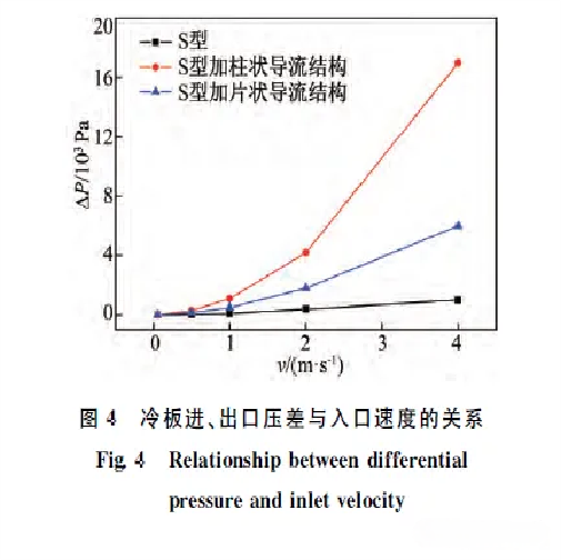
Under the same flow rate, the pressure loss of S-type cold plate is the smallest, sheet guide structurei 2ed, and the column guide structure is the largest, which is mainly due to the disturbance effect of the guide column is more obvious than others
Through analysis, it can be found that in the lower flow rate interval, the influence of the inflow structure on the pressure loss is not large. Therefore, in the process of flow channel design can choose a specific position to set up the way of infusion structure to get a better heat transfer efficiency.
2. Now, let's Optimization of flow structure
From the simulation results, it can be found that the temperature difference of parallel design is significantly reduced compared with the S-type , and the temperature difference can be as small as 1℃. Mixed flow channel on the overall temperature of the heat source is reduced again by about 1 ℃, the difference in temperature uniformity is not significant.
3. Can we improve again?
3.1 The assembling tool pressure
Through the theoretical thermal simulations, we found the best cooling loop is characterized by narrow runners and thin guide sheets. Compared with the traditional structure, it is more easy to have problems such as channel blockage and welding deformation, which affects the precision of the capability and the efficiency.
During the tests we can see reducing the thickness of brazing material is not only improving the mechanical properties, but also reduces the risk of flow channel blockage.
Pressure on the interface organization has a greater impact, in the 0.2MPa pressure brazing joint interface organization appears close welding, brazing material is completely extruded, although the mechanical properties are improved, but increased the degree of weld clogging. Therefore, under the premise of meeting the requirements of mechanical properties, while taking into account the impact of welding deformation, welding tool pressure selection of 0.1MPa or so is more appropriate.
3.2 The brazing material
from the result we can see 0.05mm welding materila can improve the channel black issue
The surface of welding is uniform, there is no obvious raw material erosion or brazing metal melting
The ultrasound scan results shown the light-colored stripes are the areas with good welding, and the brazing seams of the welding contact surface are dense, no defects such as blockage or welding deformation.
The pressure test was maintained at 1.5 MPa for 15 min, and no leakage occurred. The above results show that the process has a good welding effect on the LCP of narrow flow channel structure
Share Knowledge, Create Value
Phenicie Thermal
10/04/2024


Comentários